")
Launched in 2015 and currently used by about 20% of all VHDL FPGA designers, UVVM is one of the fastest growing verification methodologies in the EDA industry. Espen Tallaksen, CTO & Principal FPGA/ASIC Developer with Bitvis and Sunil Sahoo, Corporate Applications Engineer with Aldec, provide examples of UVVM in action.
As most readers will know, design verification now accounts for more than half of the overall project time. Verification methodologies exist to alleviate this bottleneck, where a methodology will typically include a sequencer (a means of sending data to and controlling a device under test [DUT]), models (expressing how components should behave) and a scoreboard (a means of comparing the DUT’s behaviour against the model’s).
Some solutions have been around for decades. For example, the Universal Verification Methodology (UVM) has its roots in a language developed for verification purposes in 2001. However, UVM is based on the SystemVerilog language whereas about half of the FPGA design community codes in VHDL. For them, a VHDL based verification methodology is faster and more efficient. It is even better news when it is free / open-source.
For instance, the open-source VHDL verification methodology (OS-VVM) was launched in 2012, was named the number 1 verification library in 2018 and remains extremely popular. Also, its chief developer, Jim Lewis of Synthworks, works closely with the IEEE VHDL standards group.
A more recent addition to the industry is the Universal VHDL Verification Methodology (UVVM). It was launched in 2015 and has a growing following.
So, what’s the score?
UVVM is a free methodology and library (downloadable from www.github.com/uvvm) for making structured VHDL-based testbenches. It comprises the following elements: a utility library, a VHDL verification component (VVC) framework and bus functional models (BFMs). To demonstrate these, it is best to consider a verification scenario. Figure 1 shows the test bench for a simple interrupt controller (IRQC).
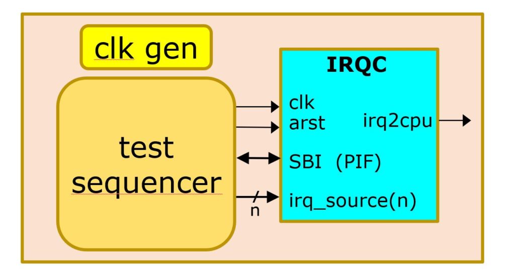
This test bench includes the DUT (i.e. the IRQC), which has a clock (clk), a reset (arst), a simple bus interface (SBI), a number (n) of interrupt sources (irq_source(n)) and the resulting interrupt to the CPU (irq2cpu). The test bench also has a clock generator and a test sequencer.
In UVVM we create the clock generator by instantiating a concurrent procedure:
Clock_generator (clk, GC_CLK_PERIOD).
Then we create a test sequencer to control the simulation. The first thing it should do is send a message to let us know it has started and is not waiting for something. In code, we might have:
log(ID_LOG_HDR, “Started simulation of IRQC_TB”).
Next, we need to check that the interrupt to the CPU is currently logic zero, if it’s not then that’s an error. Code for this might be:
check_value(irq2cpu, ‘0’, “irq2cpu default inactive”).
Then we should check signal stability, as we don’t want the interrupt to the CPU to have spikes. It should be capable of going from a stable 0 to a stable 1:
check_stable(irq2cpu, now – v_reset_time).
In the IRQC we want to generate pulses. If we wanted to put a pulse onto source number 2 the code would be:
gen_pulse(irqc_source(2), ‘1’, clk_period, “Set source 2 for clock period”).
Another important test bench feature is to wait for values, but we don’t want to forever. For example, if we’ve driven an interrupt source high, we expect the IRQC’s output go active virtually straight away, so let’s wait two 2 clock periods:
await_value(irq2cpu, ‘1’, 0 ns, 2* C_CLK_PERIOD, “Interrupt expected immediately”).
Also, most test benches need BFMs too; needed to access interfaces. We can therefore write a value (say AA) to the address of the interrupt trigger register thus…
sbi_write(C_ADDR_ITR, x”AA”, “ITR : Set interrupts”)
…and check that we can read it back with…
sbi_check(C_ADDR_IRR, x”AA”, “IRR”)
…reporting an error if we can’t.
In UVVM we can check a read against an expected value and receive time-stamped messages. For example, the sequencer code to check that a signal called ‘dout’ is 00 might be:
check_value(dout, x”00″, “dout must be default inactive”)
If all is OK, the message log might report:
60 ns irqc_tb check_value(slv x00)=> OK. dout must be default inactive.
Or, if it fails, we might receive:
ERROR:
192 ns. irqc_tb
value was: ‘xFF’. expected ‘x00’.
dout must be default inactive
The functions log (), check_value(), await_value() are just some of many in UVVM’s utility library.
VVCs
Let’s consider another BFM example. Data communications this time. Figure 2 shows a testbench for a UART.
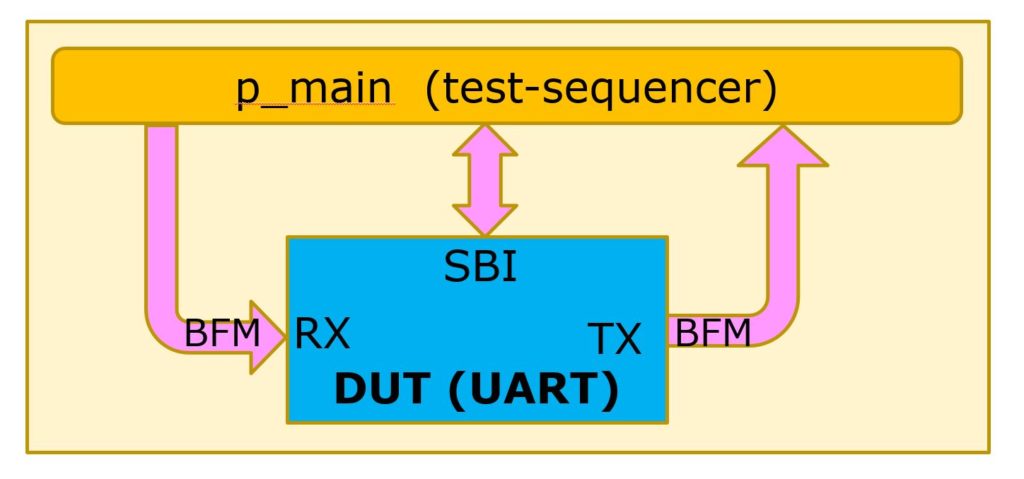
The testbench has a simple bus interface (SBI), a RX and a TX, for which we need three BFMs, and a test sequencer, p_main. To exercise the interfaces of the UART module, we could for example use:
sbi_write(C_TX, x”B3″)
…to initiate a UART serial data transfer out on TX, followed by…
uart_expect(x”B3″)
…to check the data transmitted out on the TX serial output as initiated by the above sbi_write().
Similarly, we could use uart_transmit() to apply data (e.g. x2A) on the UART RX serial input followed by sbi_check() to verify that the correct data (x2A) was received and made available in the UART RX register.
As in the IRQC example above, we can get time-stamped messages reporting success or otherwise.
But let’s exercise this UART another way, this time using our VHDL verification components. See figure 3.
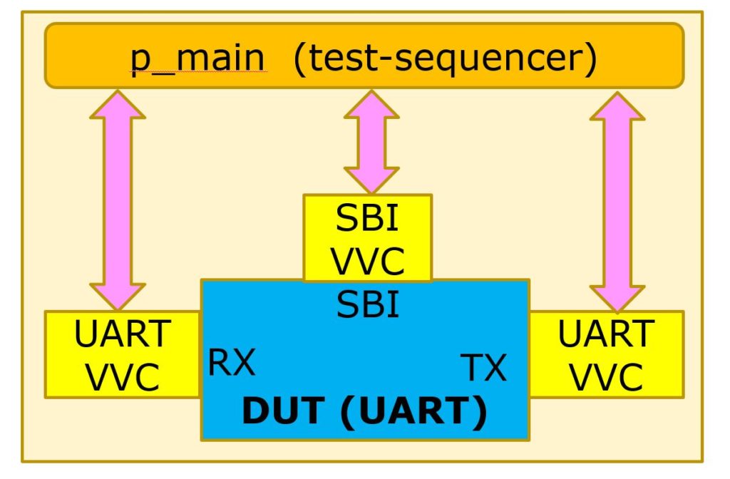
As before, we connect the DUT UART to the sequencer but this time via VVCs. This way the test sequencer doesn’t talk to the UART directly. Rather, it distributes commands to the VVCs so, for example, whereas before we used…
sbi_write(C_TX, x”B3”)
…now we use..
sbi_write(UART_VVCT,1,C_TX, x”B3”).
The additional parameters convey that we are distributing the command to instance 1 of a UART_VVC.
The benefits of using VVCs are zero time reception of commands (which allows many commands to be written at the same time to multiple VVCs, thus initiating BFM execution on several interfaces simultaneously), queued transactions are possible plus we can do lots in parallel (property checks, for example).
Perhaps the biggest boost to productivity though is a better overview and reduced workload for the sequencer. As with UVVM’s BFMs, the VVCs are open-source and free.
The VVCs in UVVM are unique when it comes to synchronizing stimuli and the checking of modules within the FPGAs and the FPGA as a whole when we have multiple interfaces, as everything can be smoothly controlled using easily readable commands from a single test sequencer. The VVCs used in the module testbenches can be easily reused in a top-level testbench for the FPGA.
What’s not to like?
UVVM provides a good, almost Lego-like verification structure. It is easy to connect BFMs and VVCs, and scripting sequences of events is like writing pseudo code.
The fact that it is open source and is so well documented means UVVM, and other free methodologies and libraries (like OS-VVM) can be downloaded and added to your EDA tool box and you can start shaving hundreds or even thousands of hours off the verification time for large and complex designs.
On a final note, in 2018, the European Space Agency (ESA) initiated a project to extend UVVM in order to provide its suppliers with a means of improving their FPGA design quality, while at the same time reducing the verification cost and schedule. This has resulted in lots of new functionality being made available for the VHDL community, especially during late 2019 and early 2020. The most important new features are Scoreboarding, Specification Coverage, Hierarchical VVCs, Error Injection and Transaction Info – which could be worth visiting in a follow-up article.