
View this article as a pdf
The RISC-V ISA has seen much adoption thanks to its customizable architecture and open-source business model. Naturally, the open-source ISA is also producing new open-source cores that target certain applications. If you are planning to take advantage of these open-source RISC-V cores in a chip of your own, you must verify its customisation and implementation. Sunil Sahoo, SW Product Manager of Aldec, discusses three different levels of verification that will give you confidence and reduce your overall development time.
In the same way the term ‘ARM-based’ is used to describe a product feature – at the chip and system level – the same is fast becoming true for RISC-V. For example, one implementation of the core, by SiFive, is at the heart of the BBC Doctor Who HiFive Inventor Kit / IoT coding platform (Ed: see EPDT news 19th November 2020). Also, Microchip claimed to be first to market with a ‘RISC-V-based SoC FPGA development kit’; the FPGA in question being the OEM’s low-power PolarFire device (Ed: see EPD news 16th September 2020).
Accordingly, RISC-V awareness stands to extend from the EDA community all the way through to end-product consumers. However, unlike the ARM architecture, the RISC-V instruction set architecture (ISA) is free and open-source. Also, while many readers may have only become aware of the ISA and cores in the last few years, RISC-V ISA development work started back in May 2010; as part of the Parallel Computing Laboratory (Par Lab) at UC Berkeley, in the USA.
RISC-V processor cores are based on the open standard ISA. In the words of RISC-V International (formerly the RISC-V Foundation, founded in 2015 and controlled by its members to drive early adoption of the core), the architecture is frozen, and software written for one RISC-V core will run on a similar one. Good news for software and systems engineers.
Good news for hardware engineers too, they have considerable flexibility over the implementation of the processor to target various applications, and can optimise it for performance, low power or security, for example. RISC-V International also points out that if you are implementing a soft RISC-V core in an FPGA then the register transfer logic (RTL) code can be easily ported into an ASIC design flow.
To date, various commercial and open-source 32- and 64-bit RISC-V cores have been implemented in hundreds of CPUs and SoC platforms. However, if you are taking advantage of the core’s availability as open-source fabless IP (for integration within a chip you are designing) you must test it for ISA compliance and functionally verify its implementation; of not only the core but also its interaction/integration with the rest of your design (e.g., other IP, memory, comms, I/O etc.).
Linting
One of the first things you should check is the quality of the hardware description language (HDL, such as VHDL or SystemVerilog) code that effectively defines your implementation and customisation of the core. For this, a linting tool can be used for static verification; i.e., there is no need to dynamically stimulate the design (at this stage).
Linters are available with RISC-V rules plugins, based on industry best-practice processor system static analysis, where the rules will typically belong to sets that will include:
- Coding Styles. These verify the correctness of constants and variable usage, port definitions, instantiations and object references. For example, this rule verifies that for each constant, its bit width value is matched with the base number part, that there are no continuous assignments on input ports and references on output ports, and that all declared objects are assigned and referenced.
- Data Types and Operations. These verify the correct use of Verilog or SystemVerilog data types in expressions. For example, if you wish to compare the contents of an 8-bit register with the contents of a 16-bit one it is dangerous to do so without first zeroing the upper byte of the larger register. Fig 1 shows perfectly valid code for the comparison, but a good linter will flag the risk of functional errors arising if the upper byte of the 16-bit register contains non-zero values.
- Coding for Implementation. These check for optimal synthesis; timing closure as well as resets and the finite state machine (FSM) implementation. They ensure an absence of undesired latches, the implementation of a proper reset method and simulation-to-synthesis functional equivalency.
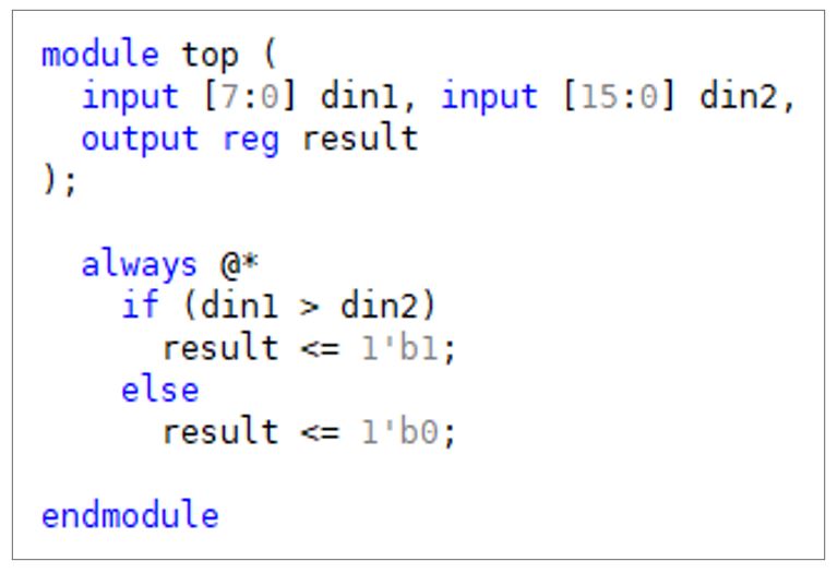
Figure 1 – Above valid HDL used to describe the behaviour of hardware but risky if bits 8 to 15 of din2 are not zeroed first.
Linting ensures HDL code robustness by flagging absolute errors and warning of best-practice infringements early on in your design flow. This is good because dynamic simulations take time [days, for large designs] to run, time that is best spent looking for dynamic performance issues and not code quality issues that could have been found through linting in a matter of minutes.
Simulation (under UVM)
This effectively exercises the core (still as code) using a testbench. By way of an example, let’s consider how we might verify the popular Ibex core from lowRISC under the universal verification methodology (UVM).
Ibex is an open-source 2-stage 32-bit RISC-V core written in SystemVerilog. To simulate it under UVM we will need:
- A SystemVerilog simulator that supports UVM;
- A RISC-V instruction set simulator (ISS, such as Spike or OVPsim); and
- A complier and an assembler to ready the code for simulation.
We also need a testbench, such as the open-source RISC-V DV random instruction generator developed by Google. The testbench generates compiled instruction binaries used to stimulate the core. Figure 2 shows the testbench and core.
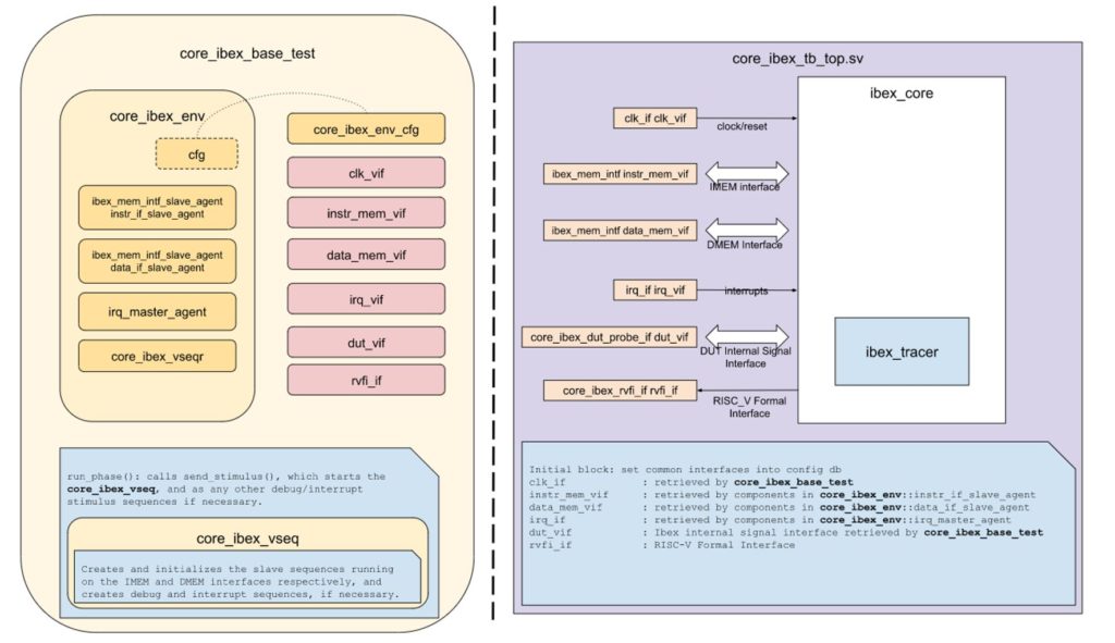
Figure 2 – On the left we have the testbench, with the rounded-corner blocks representing SV dynamic objects. On the right we have the Ibex core, with the square blocks representing SV static modules. (image source: https://ibex-core.readthedocs.io/en/latest/verification.html)
The results (of the RTL simulation) can then be compared against a golden model generated by the instruction set simulator (ISS). See figure 3.
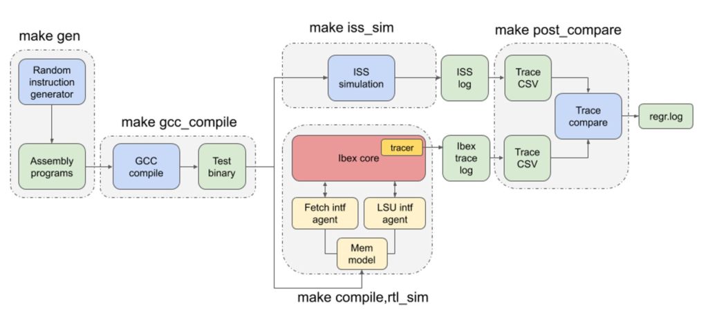
Figure 3 – Above, the RTL simulation and ISS are compared when the core is stimulated using random instructions designed to dynamically verify the RISC-V. (image source: https://ibex-core.readthedocs.io/en/latest/verification.html)
Hardware in-the-loop
As mentioned, if you are implementing a soft RISC-V core in an FPGA then the RTL code can easily be ported into an ASIC design flow. This is particularly good news if you are designing a SoC, as real hardware can be used for hardware-assisted verification. Moreover, the same hardware can be used at three stages (see figure 4).
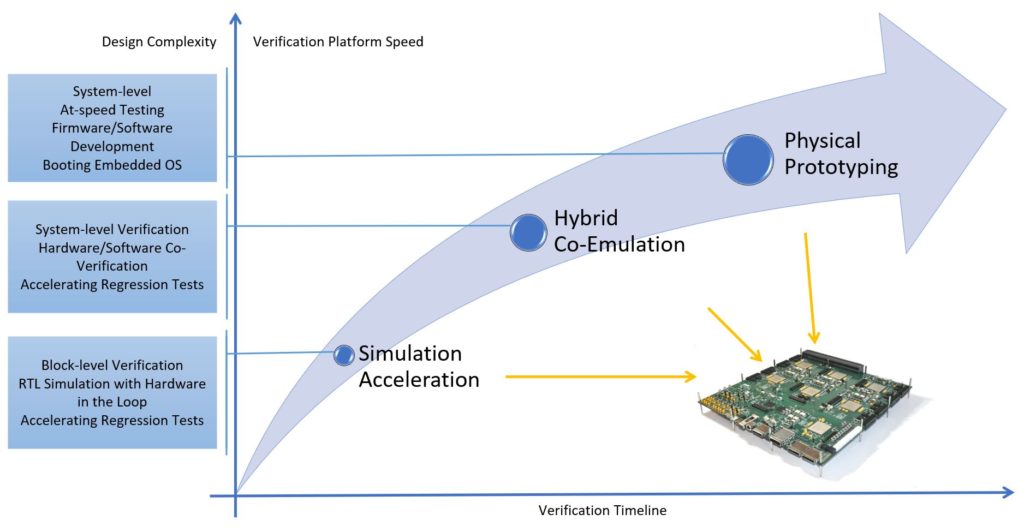
Figure 4 – Hardware-assisted verification benefits hardware, software and systems engineers alike, and shortens overall project development time.
For anyone designing a SoC that will include one or more RISC-V application cores, projects can be de-risked and fast-tracked by using FPGA-based prototyping platforms. Many are modular and, through the use of high-speed backplanes, can be interconnected to accommodate designs of up to several hundred million gates. Also, daughter card availability tends to mirror industry’s requirements for peripheral interfaces, such as cameras and embedded vision drivers and reference designs for applications such as such as advanced driver assistance systems (ADAS).
In summary, it is great that the RISC-V core is available as open-source IP. The challenge is verifying that your implementation / customisation of the core is ISA-compliant (so that your end-product can be officially promoted as ‘RISC-V-based’), functionally correct and that it works with the rest of your system.